EM11 series high performance Vector control inverter

>> For more information visit our new website www.sah.co.rs <<


EMC Certification

LVD Certification

Manual


Techniclal Specifications 

Models

Dimensions

Technical Specifications

Item

Specification 

Standard functions

Maximum frequency

Vector control: 0~300 Hz
V/F control: 0~3000 Hz

Carrier frequency

0,5~16KHz
(Noseča učestanost se automatski menja prema karakterisikama opterećenja )

Input frequency resolution 

Digital setting: 0.01 Hz
Analog setting: maximum frequency x 0.025%
 

Control mode 

Sensor-less vector control (SVC)
Closed-loop vector control (VC)(+ PG card)
Voltage/Frequency (V/F) control

Startup torque 

G type: 0.5 Hz/150% (SVC); 0 Hz/180% (VC)
P type: 0.5 Hz/100%
 

Speed range 

1:100 (SVC)

Speed range 

Speed stability accuracy 

± 0.5% (SVC)  ± 0.02% (VC) 

Torque control accuracy 

± 5% (VC)

Overload capacity 

G type: 60s for 150% of the rated current, 3s for 180% of the rated current
P type: 60s for 120% of the rated current, 3s for 150% of the rated current
 

Torque boost 

Auto boost
Manual boost 0.1%~30.0%

V/F curve 

Straight-line V/F curve
Multi-point V/F curve
N-power V/F curve (1.2-power, 1.4-power, 1.6-power,1.8-power, square)

V/F separation  

Two types: complete separation; half separation

Acceleration/deceleration curve

Straight-line ramp
S-curve ramp
Four groups of acceleration/deceleration time with the range of 0.0s~65000s
 

DC braking 

DC braking frequency: 0.00 Hz~maximum frequency
Braking time: 0.0s~36.0s
Braking trigger current value: 0.0%~100.0%
 

JOG control

JOG frequency range: 0.00Hz~50.00 Hz
JOG acceleration/deceleration time: 0.00s~6500.0s
 

Built-in simple PLC, multiple speeds

It realizes up to 16 speeds via the simple PLC function or combination of DI terminal states 

Built-in PID 

It realizes closed loop control system easily 

Auto voltage regulation
(AVR)

It can keep constant outputvoltage automatically when the mains voltage fluctuation. 

Overvoltage/Over current
stall control

The current and voltage are limited automatically during the running process so as to avoid frequently tripping due to overvoltage/over current. 

Rapid current limit
function
 

It can auto limit running current of frequency inverter to avoid frequently tripping

Torque limit and control 

(Excavator characteristics) It can limit the torque automatically and prevent frequently over current tripping during the running process. Torque control can be implemented in the VC mode 

Individualized functions 

High performance 

Control of asynchronous motor and synchronous motor are implemented through the high-performance current vector control technology

Instant power off not stop

The load feedback energy compensates the voltage reduction so that the frequency inverter can continue to run for a short time. 

Rapid current limit

To avoid frequently over current faults of the frequency inverter. 

Virtual I/O

Five groups of virtual DI/DO can realize simple logic control. 

Timing control 

Time range: 0.0~6500.0 minutes 

Multi-motor switchover 

Two motors can be switched by two groups of motor parameters. 

Multiple communication
protocols
 

It supports communication bus via Modbus-RTU, PROFIBUS-DP, CANlink and CANopen 

Motor overheat protection 

The optional I/O extension card enables AI3 to receive the motor temperature sensor input (PT100, PT1000) so as to realize motor overheat protection

Multiple encoder types

It supports various encoders such as differential encoder, open-collector encoder, resolver, UVW encoder, and SIN/COS encoder.

Advanced background software 

It supports the operation of frequency inverter parameters and virtual oscillograph function,by which the state of frequency inverter can be monitored 

RUN 

Running command giving

Key panel, Control terminals, Serial communication port, You can switch between these giving in various ways. 

Frequency giving

There are 10 kinds frequency giving: digital setting, analog voltage setting, analog current setting, pulse setting and serial communication port setting. You can switch between these giving in various ways 

Input terminal 

6 digital input (DI) terminals,
one of which supports up to 50 kHz high-speed pulse input
2 analog input (AI) terminals,
one of which only supports 0V~10 V voltage input
and the another supports 0V~10 V voltage input or 0~20 mA current input. Many DI terminals 1 AI terminal that supports -10V~10 V voltage input
 

Output terminal 

1 high-speed pulse output terminal (open-collector) that supports 0–50 kHz square wave signal output.
1 digital output (DO) terminal.
1 relay output terminal.
2 analog output (AO) terminals, one of them supports 0~20 mA current output or 0V~10 V voltage output expanding capacity,
many DO terminals.
many relay output terminals.

Display and
keypad
operatio
n
 

LED display 

It displays the parameters 

Key locking and function selection

It can lock the keys partially or completely and define the function range of some keys so as to prevent misoperation

Protection mode 

Motor short-circuit detection at power-on, input/output phase loss protection, over current protection, overvoltage protection, less voltage protection, overheatprotection and overload protection,etc 

Environment 

Installation location

Indoor, no direct sunlight, dust, corrosive gas, combustible gas, oil smoke, vapour, drip or salt. 

Altitude 

Lower than 1000 m

Ambient temperature 

-10°C~+40°C
(de-rated if the ambient temperature is between 40°C and 50°C)

Humidity 

Less than 95%RH, without condensing 

Vibration 

Less than 5.9 m/s2 (0.6 g)

Storage temperature 

-20°C ~ +60°C

Back to Top▲▲


Models

Three-phase 380VAC, 50/60Hz
Model Adaptable motor Input current Output current
KW HP A A
EM11-G3-1d5 1,5 2 5 3,8
EM11-G3-2d2 2,2 3 5,8 5,1
EM11-G3-004 3,7 5 10,5 9
EM11-G3-5d5 5,5 7,5 14,6 13
EM11-G3-7d5 7,5 10 20,5 17

Back to Top


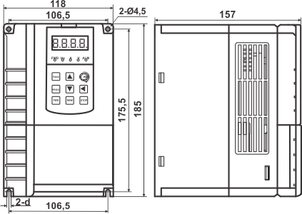
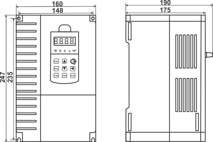
Dimensions

EM11-G3-1d5, EM11-G3-2d2, EM11-G3-004 EM11-G3-5d5, EM11-G3-7d5
Back to Top