|
1
|
Encoder
series (Example ISC)
|
|
2
|
Encoder
body diameter (Example 38 mm)
|
|
3
|
Encoder
shaft diameter (Example 6 mm)
|
|
4
|
Constructional
code
|
|
5
|
Encoder
connection
|
|
C:
|
Side connector
|
H:
|
Back connector
|
G:
|
Side cable
|
E :
|
Back cable
|
J:
|
Square side connector
|
T:
|
Square back connector
|
|
|
6
|
The
number of pulses per round (Example 1024)
|
|
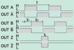
7
|
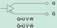
Output
signal
|
|
A:
|
A signal
|
AL:
|
A i Z signal 
|
AZ:
|
A i Z signal 
|
|
B:
|
A i B signal
|
BL:
|
A, B i Z signal
|
AZ:
|
A, B i Z signal
|
|
|
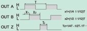
8
|
Width
of the reference signal Z.
No number no Z signal, 1: TZ=1T, 2:
TZ=1/2T, 3: TZ=1/4T,
|
|
9
|
Power
supplay
|
|
5
|
5 VDC
|
5-12
|
5~12 VDC
|
12-24
|
12~24 VDC
|
|
|
10
|
Output
Type
|
|
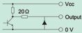
C:
|
Open collector NPN
|
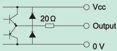
F:
|
Push pull
|
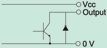
E:
|
Voltage output (PNP)
|
L:
|
Line driver AM26LS31
|
|
H:
|
Line driver MC3487
|
D:
|
Line driver MC3487
|
T:
|
Line driver 26ET31B
|
|