|
|
>> For more information visit our new website www.sah.co.rs << |
|
||||||||||
|
|
>> For more information visit our new website www.sah.co.rs << |
|
||||||||||
|
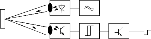
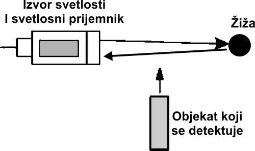
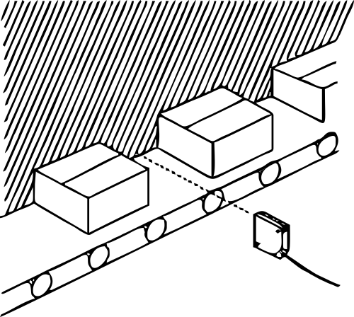
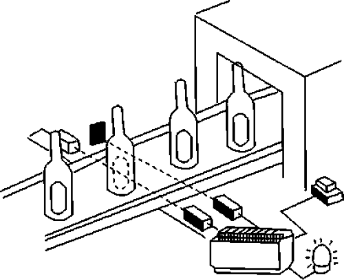
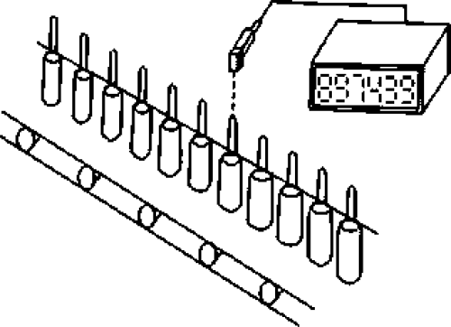
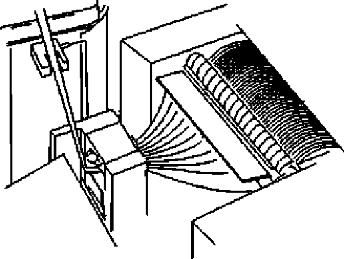
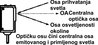
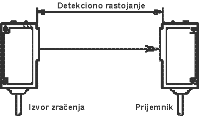
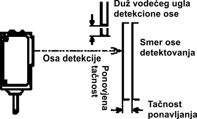
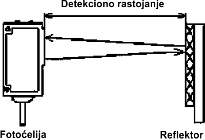
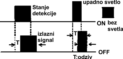
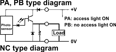
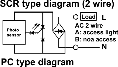
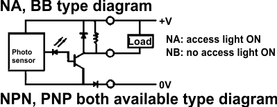
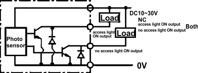
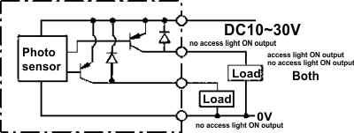
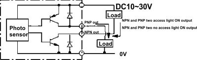
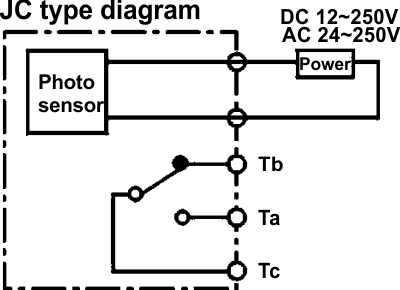
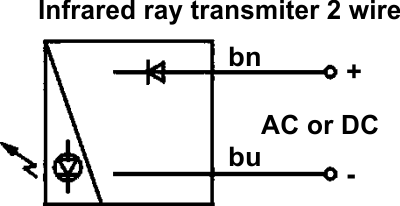
Operating Principles |
|
||||||||||
| Back To Top ▲ |
|
||||||
| Back To Top ▲ |
|
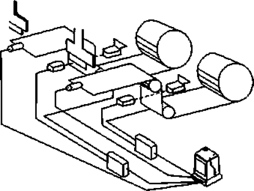
Model selection guide |
 |
||||||||||||||||||||||||||||||||||||||||||||||||||||||||||||||||||||||||||||||||||||
|
||||||||||||||||||||||||||||||||||||||||||||||||||||||||||||||||||||||||||||||||||||
| Back To Top ▲ | ||||||||||||||||||||||||||||||||||||||||||||||||||||||||||||||||||||||||||||||||||||
|
||||||||||||||||||||||
| Back To Top ▲ |
|
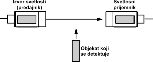
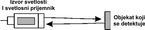
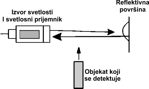
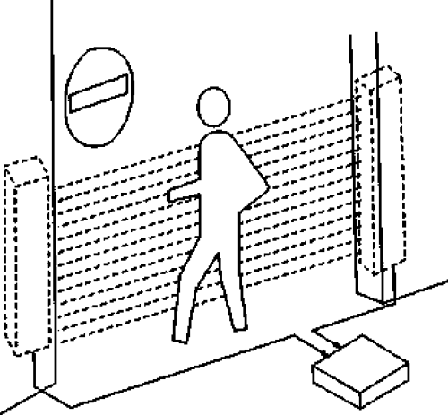
Characteristics and Reflection |
|
||||||
| Back To Top ▲ |
| Notes |
|
To correlation
type and
feedback
reflection
type
The
set distance
should be less
than the
detection
distance
stipulated in
the operation
instruction.
Because of
keeping a
room, although
it can work
when the set
distance is
bigger than
the stipulated
detection
distance, the
performance
cannot be
guaranteed. In
addition,
please make
sure to keep
certain room
in the bad
environment
with rubbish
and dust when
setting a
distance. |
||||||||||||||||||||||||
|
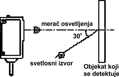
To diffused
reflection
type
The
detection
distance shown
in the
specification
manual is in
accordance
with standard
detected
object. Actual
detection
distance will
change in pace
with the
change of the
size, color,
surface
evenness of
detected
object. Please
ensure the
stipulated
room when set
distance. |
||||||||||||||||||||||||
|
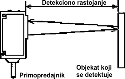
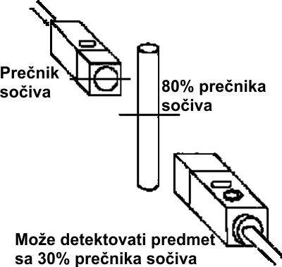
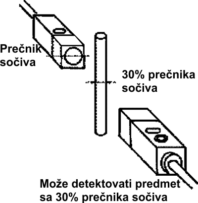
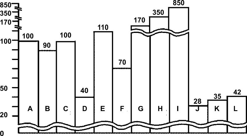
According
to the change of
detected object
size and variation
regulation of
detection
distance, bigger
detected object,
bigger reflection
volume, longer
detection
distance. But when
the size of optic
receiving surface
is bigger than the
size of the
detected object,
the detection
distance won't
increase even if
the object size
increase again. |
||||||||||||||||||||||||
|
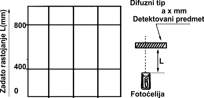
The difference between different detection distances of the detected object (Apply to scattered reflection type). |
||||||||||||||||||||||||
 |
||||||||||||||||||||||||
|
||||||||||||||||||||||||
| Back To Top ▲ |
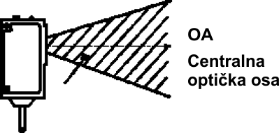
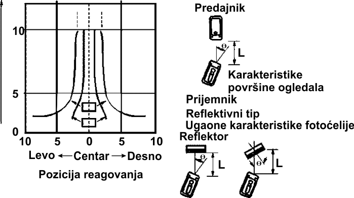
| Precautions and methods of preventing multiple interference |
|
An unstable reaction is caused by an external light or from other sensor and this phenomenon is called multiple interferences. |
|||||||||||||||||||||||||||
|
|||||||||||||||||||||||||||
| When installing, consider the following draft | |||||||||||||||||||||||||||
|
|||||||||||||||||||||||||||
| Back To Top ▲ | |||||||||||||||||||||||||||