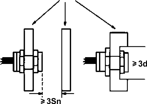
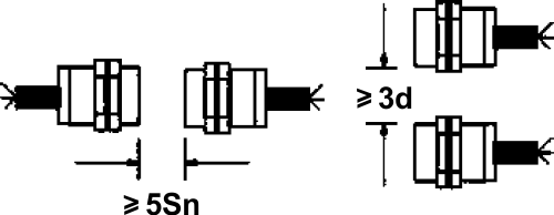
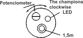
The
size of
detection object and
detection distance
|
If
the
detection object is
square metal sheet
with constant
thickness
(t=1mm), detect at
detection distance X
when change its side
length d
mm.
|
When
the detected
object is bigger than
standard detected
object, on the main, the
detection distance is
constant.
According to different
machine type, sometimes
the features will be
different with that
mentioned on the left.
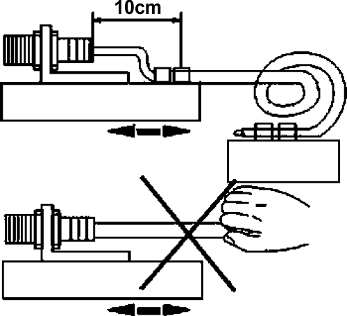
To through type, the
detection object is like
cylinder metal bar.
|
The
thickness of
detected object and
detection distance
|
Detect
at
detection distance X
mm (front detector)
when change the
thickness
of the assigned
standard detected
object 1 mm.
|
For
more than 1
mm thick magnetic
metal like iron, on
the main, the
detection distance
will not change.
|
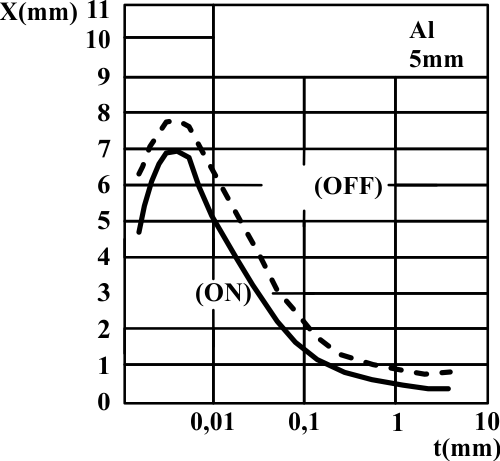
| The
effects
resulted from the
thickness of detected
object and cladding
material |
Because
the
detection to standard
detected object will
be effected by its
shape, size, material,
and various cladding
material, confirm
through
detection distance X
mm measurement.
|
The effects
resulted from detection
distance and cladding
material of the metal
excluded iron will be
different according to
different machine type.
On
the main, the machine
type which
detects all the metals
will not ne effected by
cladding material.
|