|
|
>> For more information visit our new website www.sah.co.rs << |
|
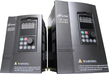 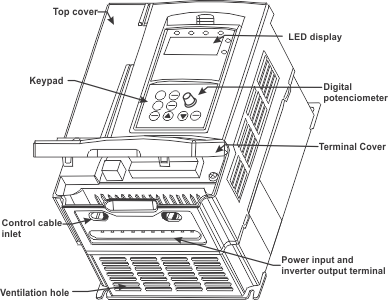 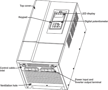 |
|
|
>> For more information visit our new website www.sah.co.rs << |
|
   |
| Main Features |
|
|||||||||||||||||||||||||||||||||||||||||||||||||||||||||||||||||||||||||||||||||||||||||||||||||||||||||||||||||||||||||||||||||||||||
| Back To Top ▲ | |||||||||||||||||||||||||||||||||||||||||||||||||||||||||||||||||||||||||||||||||||||||||||||||||||||||||||||||||||||||||||||||||||||||
|
|||||||||||||||||||||||||||||||||||||||||||||
| Back To Top ▲ | |||||||||||||||||||||||||||||||||||||||||||||
| Adequate Braking Resistors |
|
||||||||||||||||||||||||||||||||||||||||||||||||||||||||||||
| Back To Top ▲ | ||||||||||||||||||||||||||||||||||||||||||||||||||||||||||||
| Mounting Sizes |
|
|||||||||||||||||||||||||||||||||||||||||||||||||||||||||||||||||||||||||||||||||||||||
|
|||||||||||||||||||||||||||||||||||||||||||||||||||||||||||||||||||||||||||||||||||||||
| Back To Top ▲ | |||||||||||||||||||||||||||||||||||||||||||||||||||||||||||||||||||||||||||||||||||||||
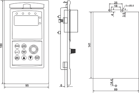
| Panel Dimensions |
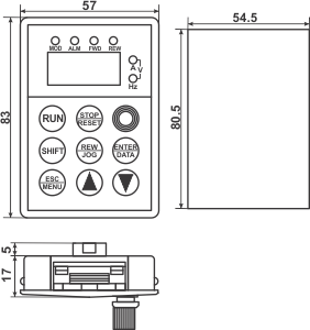  |
| Back To Top ▲ |
| Failure code | Failure type | Possible reason | Countermeasure |
| E001 | Overcurrent
during accelerating process |
Accelerating time is too short | Prolong accelerating time |
| Improper V/F curve | Adjust V/F curve
setting,adjust manual torque boost or change to automatic torque boost |
||
| Restart rotating motor | Set deceleration restart function | ||
| Low power source voltage | Check input power supply | ||
| Too small power of the inverter | Choose inverter with high-power | ||
| E002 | Overcurrent
during decelerating process |
Decelerating time is too short | Prolong decelerating time |
| Have
potential
energy load or big inertia load |
Increase braking
power of external energy consumption braking subassembly |
||
| Power of inverter is a bit small | Choose inverter with high-power | ||
| E003 |
Overcurrent
during constant speed process |
Load change suddenly or have unwonted phenomena | Check or reduce break of the load |
| Accel/Decel time is set to too short | Prolong accelerating decelerating time properly | ||
| Low power source voltage | Check input power supply | ||
| Power of inverter is a bit small | Choose inverter with high-power | ||
| E004 | Overvoltage
during accelerating process |
Unwonted input voltage | Check input power supply |
| Accel time is set to too short | Prolong accelerating time properly | ||
| Restart rotating motor | Set speed checking restart function | ||
| E005 | Overvoltage
during decelerating process |
Decelerating time is too short | Prolong decelerating time |
| Have
potential energy load or big inertia load |
Increase braking power of external energy consumption braking subassembly | ||
| E006 | Overvoltage
during constant speed process |
Unwonted input voltage | Check input power supply |
| Accel/Decel time is set to too short | Prolong accelerating decelerating time properly | ||
| Input voltage change abnormally | Assemble reactor | ||
| Load inertia is a bit big | Use energy consumption subassembly | ||
| E007 | Inverter
control power supply overvoltage |
Unwonted input voltage | Check input power supply or look for service |
| E008 | Inverter overload |
Accel time is set to too short | Prolong accelerating time |
| DC injection braking is too big | Reduce DC injection braking current,prolong braking time | ||
| Improper V/F curve | Adjust V/F curve and torque boost | ||
| Restart rotating motor | Set speed checking restart function | ||
| Power source voltage is too low | Check power source voltage | ||
| Load is too big | Choose inverter with high-power | ||
| E009 | Motor overload | Improper V/F curve | Adjust V/F curve and torque boost |
| Power source voltage is too low | Check power source voltage | ||
| General motor run at low speed with big load | Can choose frequency conversion motor for long time low speed run | ||
| Motor overload protection factor set incorrectly | To set motor overload protection factor correctly | ||
| Motor blocked up or load change too suddenly and quickly | Check the load | ||
| E010 | Inverter
over heating |
Air-path blocked | To clear air-path or improve ventilation condition |
| Ambient temperature is too high | Improve ventilation condition, lower carrier frequency | ||
| Fan damaged | Replace the fan | ||
| E011 | Reserved | Reserved | Reserved |
| E012 | Reserved | Reserved | Reserved |
| E013 | IGBT failure | Transient overcurrent of the inverter | Refer to countermeasure for overcurrent |
| Phase to phase short circuit or earthing short circuit of output 3 phase | Wiring again | ||
| Connecting wire or insert on control board loose | Check and connect the wire again | ||
| Unwonted current wave caused by missing output phase etc. | Check wiring | ||
| Assistant power supply damaged and drive voltage lacking | Look for service from manufacturer or agent | ||
| Unwonted control board | Look for service from manufacturer or agent | ||
| E014 | External
device failure |
Use sudden stop key (STOP) in non-keypad run mode | Look up operation mode |
| Use sudden stop key (STOP) under condition of stall | Set running parameter correctly | ||
| Sudden stop terminal for external failure closed | Open external failure terminal after external failure is settled | ||
| E015 | Current detecting circuit failure |
Connecting wire or insert on control board loose | Check and connect the wire again |
| Assistant power supply damaged | Look for service from manufacturer or agent | ||
| Hall component damaged | Look for service from manufacturer or agent | ||
| Unwonted amplifying circuit | Look for service from manufacturer or agent | ||
| E016 | RS485 communication failure |
Baud rate set improperly | Set Baud rate properly |
| Serial port communication error | Press STOP/RESET key to reset,look for service | ||
| Failure warning parameter set improperly | Modify F2.16, F2.17 | ||
| Upper device doesn’t work | Check if upper device work and wiring is correct | ||
| E017 | Overcurrent
in setting |
Inverter Lower power | Select the suitable power inverter |
| E018 | Over
volt. in setting |
When processing motor rotating setting and starting to decelerate, there is over volt. caused by big inertia | Configurating external dynamic braking assembly or corresponding braking power |
| E019 | Under
voltage failure |
Under voltage | Check spot input voltage |
| E020 | Reserved | ||
| E021 | Failure.not
remove.or hardware circuit failure |
Failure not remove hardware circuit failure | Remove failure, inspect hardware, Look for service |
| E022 | Reserved | Reserved | Reserved |
| E023 | Reserved | Reserved | Reserved |
| P.OFF | DC
bus-bar under vlot. |
Input power supply unusual | Check spot input voltage |
| Back To Top ▲ | |||