|
|
>> For more information visit our new website www.sah.co.rs << |
 |
|
||||||||||||||||||||||||||||||||||||||||||||||||
|
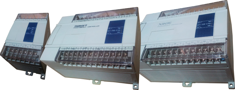
Main Features |
|
|||||||||||||||||||||||||||||||||||||||||||||||||||||||||||||||||||||||||||||||||||||||||||||||||||||||||||||||||||||||||||
| Back To Top ▲ | |||||||||||||||||||||||||||||||||||||||||||||||||||||||||||||||||||||||||||||||||||||||||||||||||||||||||||||||||||||||||||
 |
||||||||
|
||||||||
| Back To Top ▲ |
| Electrical Specification |
|
|||||||||||||||||||||
| Back To Top ▲ |
|
Input Specifications |
|
||||||||||||||||||||||||
| Back To Top ▲ |
|
|||||||||||||||||||||||||||||||||||||
| Back To Top ▲ | |||||||||||||||||||||||||||||||||||||
XC1-16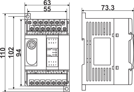 |
XC1-24/XC1-32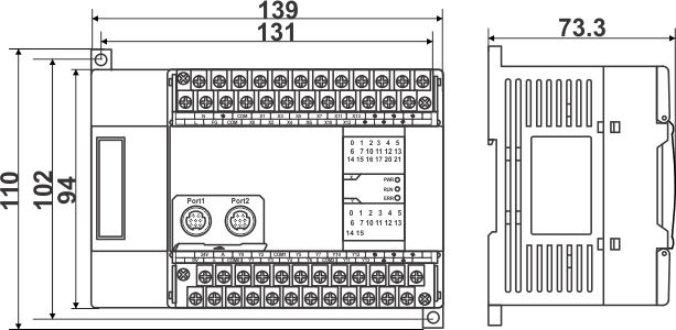 |
| Back To Top ▲ |
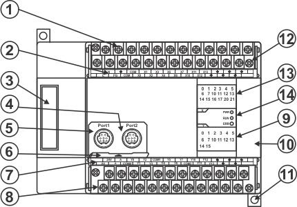
| Each Part's Description |
 |
||||||||||||||||||||||||||||
|
||||||||||||||||||||||||||||
| Back To Top ▲ |
|
||||||||||||||||||||||||||||||||||||||||||||||||||
| Back To Top ▲ | ||||||||||||||||||||||||||||||||||||||||||||||||||