|
>> For more information visit our new website www.sah.co.rs <<
|
|
|
||||||||||||||||||||||||||||||||||||||||||||||||||||||||||||||||||||||||||||||||||||||||||||||||
|
||||||||||||||||||||||||||||||||||||||||||||||||||||||||||||||||||||||||||||||||||||||||||||||||||||||||||||||||||||||||||||||||||||||||||
|
|
||||||||
|
||||||||

|
|||||||||||||||||||||
|
||||||||||||||||||||||||
|
|||||||||||||||||||||||||||||||||||||
|
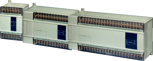
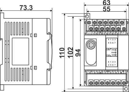
XC3-14 |
|
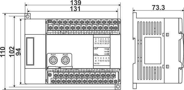
XC3-24/XC3-32 |
|
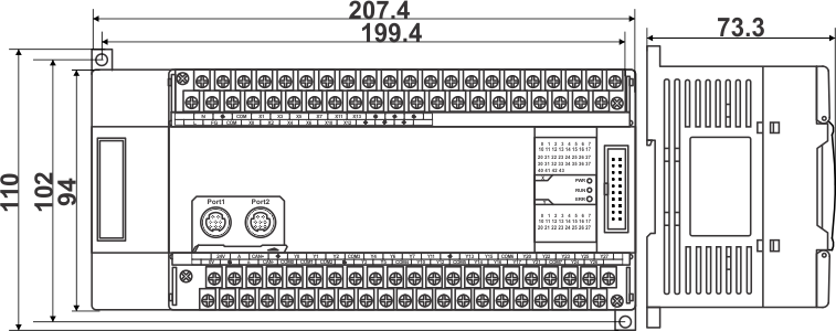
XC3-48/XC3-60 |
|
|
||||||||||||||||||||||||||||||||||||||
|
||||||||||||||||||||||||||||||||||||||
PLC 220 VAC 220 VAC 220 VAC 220 VAC 220 VAC
Inputs
Outputs
PNP
NPN
Analogue
Transistor (NPN)
Relay
Napajanje
XC3-14PR-E
8
2
4
XC3-14PRT-E
8
-
6
XC3-14PT-E
8
6
-
XC3-14PT-C
8
6
-
24VDC
XC3-24PRT-E
14
2
8
XC3-24PT-E
14
10
-
XC3-24PT-C
14
10
-
24VDC
XC3-24PR-C
14
-
10
24VDC
XC3-32PR-E
18
-
14
220 VAC
XC3-32PRT-C
18
2
12
24VDC
XC3-32PRT-E
18
2
12
220 VAC
XC3-32PT-E
18
14
-
220 VAC
XC3-48PT-E
28
20
-
220 VAC
XC3-48PRT-E
28
2
18
220 VAC
XC3-48RT-E
28
2
18
220 VAC
XC3-60PRT-E
36
2
22
220 VAC
XC3-60PT-E
36
24
-
220 VAC
XC3-19AR-E
9
8 12Bit 0~10V
-
10
220 VAC
Gore ▲